“三角洲” 是一种机器人或打印机,其头部运动是依靠呈三角摆放的三对并联臂。一对平行的并联臂保持头部的水平,并联臂的运动使头部在三个维度上自由移动。三角洲有很多的方案,有些是可以简单制作使用的。
并联臂有两种常见方案:
- 每个并联臂对都安装在一个主关节上,产生的运动是这个主关节的旋转。这种结构一般被称为 旋转三角洲(Rotational Delta)或由发明者名字命名的“克拉维尔三角洲”(Clavel Delta)。广泛应用于电子、食品等众多行业里的分拣机器人。该机型的设计可以看看 Energetic 或 FirePick 的打印机。
- 并联臂连接到沿平行运动导轨上,这种结构一般被称为线性三角洲。是 3D 打印机世界中最常用的结构,起源于 Rostock 和 Kossel。 不能用专业术语称他为“平行三角洲”(Parallel Delta),因为所有具有平行臂的机器人都称为平行机器人。
还有另一种没有刚性框架的方案是将头部悬挂在绳子上用绳子驱动。 有几个例子是 Skydelta 和 suspended delta的。
线性三角洲的运算很简单,因为滑块沿直线运动的,所以头部的水平运动与机架的垂直运动通过勾股定理(对角线长度的平方等于三角形边的平方和,三角形有人必须是直角三角形)。 这里对角线是臂长,常数,垂直分支是平台和托架的相对垂直位置,水平分支是平台和托架的相对水平位置。
数学不难,但对于3D打印机来说必须做很多平方根。 基于8位处理器的主板很辛苦的计算,对这些用8位处理器的三角洲进行了很多软件优化。 32位主板正在成为三角洲打印机更常见的主板选择,因为它们具有更快的处理器。 在不对称设计进行了测试,三个滑块可以在非等边三角形上,尤其是角度为 90° 和 180° 的“方形”三角洲。
¶ 线性三角洲
¶ 原理图
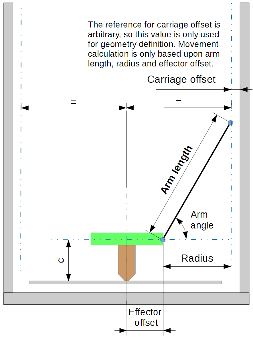
以效应器为中心的臂角是并联臂长度、最小角度和并联臂在最大直径时的角度的结果。 对于 20° 的最小角度,对于最大直径的臂垂直线,该角度约为 60°,但如果增加最小角度,它可能会更高。 22° 的最小角度将与垂直臂产生 63° 的角度。
由于间隙问题,尤其是冷却风扇或效应器附件,并联臂可能无法达到垂直角度。 在这种情况下,对于给定的最小角度,臂长可能会减少,而效应器处于中心时的角度会更低。
另一方面,一些打印机的手臂能够垂直越过(例如 Rostock Max)。

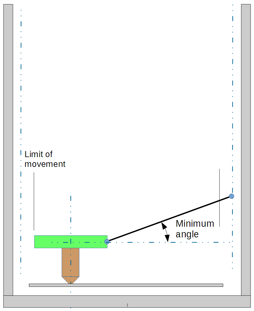
当效应器处于最大直径时,最小臂角是基本设计参数之一。 它对效应器的稳定性、精度和滑架速度很重要。 对于给定的效应器水平速度,低角度会导致高滑架速度。 低角度也会降低效应器的稳定性。 一般来说,20°角被认为是一个实际的最小值,并导致滑架速度比效应器水平速度高2.75倍。 一些理论上最小角度为 15° 的打印机可能会在其最大直径处出现失步。
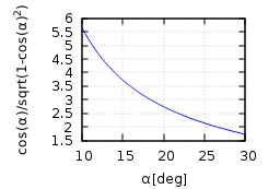
壁杆角度的加速系数
| 角度 | 速度倍数 |
| 22.5° | 2.41 |
| 20° | 2.75 |
| 17.5° | 3.17 |
| 15° | 3.73 |
| 12.5° | 4.51 |
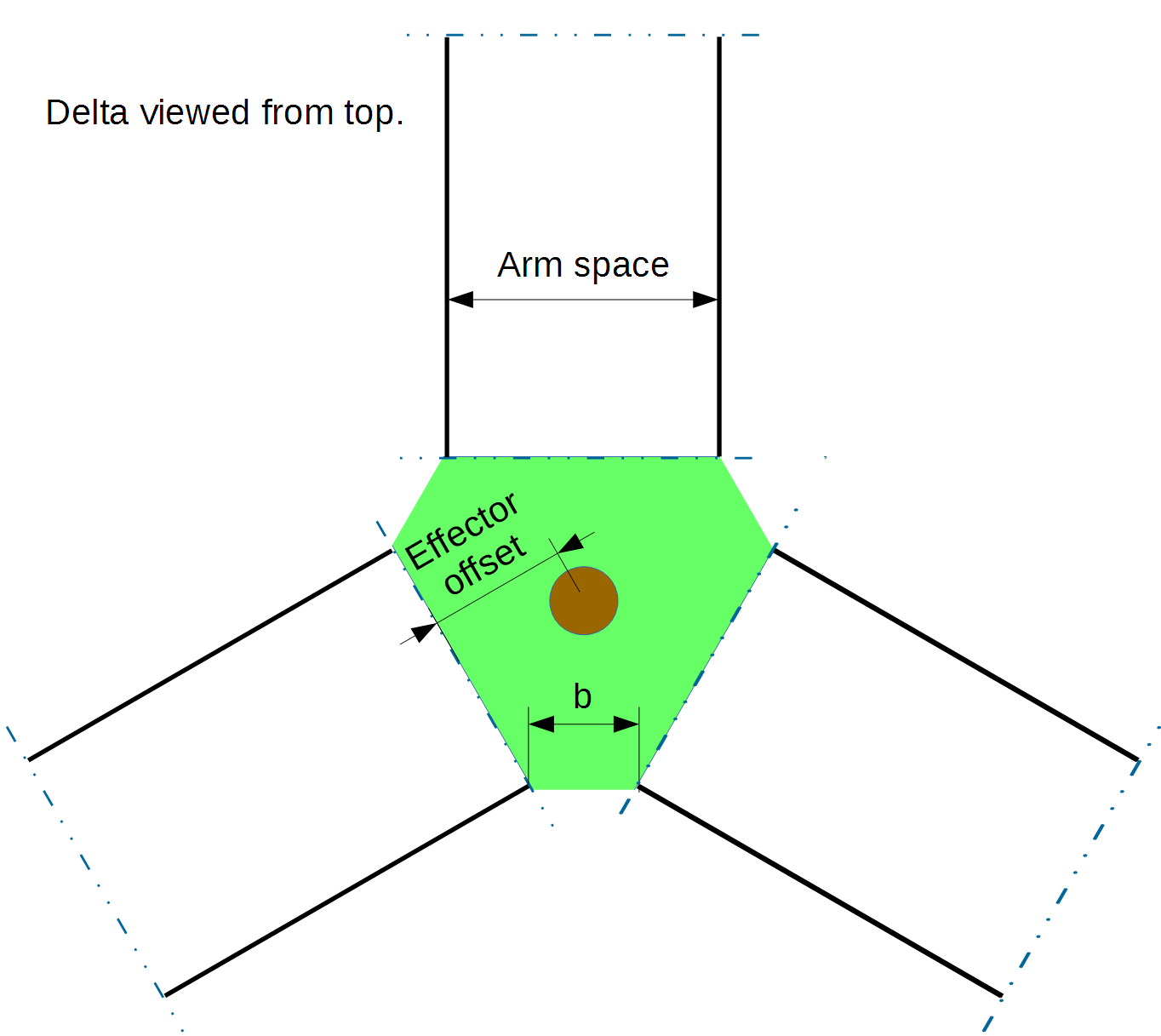
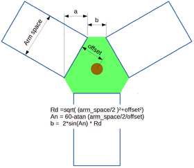
手臂空间不影响运动计算,但对效应器稳定性很重要。 最小偏移获得最佳稳定性,该偏移具有最大可能的臂空间(最小化 b 尺寸)。
¶ 运动范围
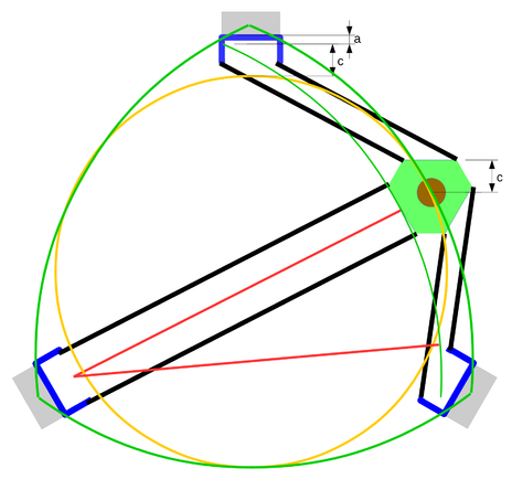
对于给定的最小角度,可到达区域是一个带有凸出边的三角形,三角形的末端朝向柱子,在不影响柱子的情况下无法进入。 然后,为简单起见,可到达区域通常被认为是圆形的。 当一个人想在打印区域中刻一个矩形或正方形时,评估真正的可到达区域可能会很有趣。 配件(皮带和风扇)对于实际可用区域至关重要。
示意图
- 绿色:可以无障碍到达的区域
- 橙色:考虑到效应器和立柱之间所需间隙的实际区域。
¶ 运动方向和轴名称
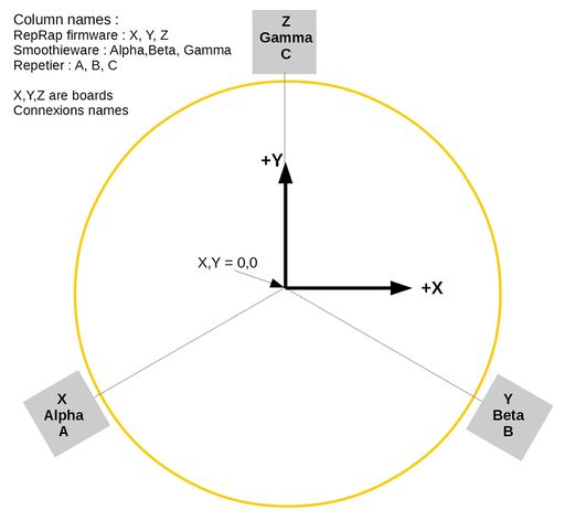
View from top
¶ 效应器稳定性
¶ 什么是效应器稳定性?
This is the fact that an effector resist to tilting moments. The tilt may displace the hotend nozzle and creates imprecision. It also have an effect on level measurement sensor while the sensors are offset from the hotend. Two things have important effect on an effector stability:
- The geometry, as different geometries may induce higher or lower loads on arms and articulation, so higher or lower deformation. A geometry reducing the load will increase precision.
- The moment resistance induced by arm articulation, say a cardan will resist to torsion induced by the effector, while ball articulation will not.
The moment which will induce tilt will be created by :
- Inertia
- Load on the nozzle
¶ 如何改善结构
- A small offset will reduce the load on arms/articulation for a moment and shall be researched.
- For a given offset, the distance between the centers of articulation (noted 'b' on drawing) will modify the moment created by side loads. The lower this space, the better the stability. When these articulation are merged, the geometric stability is very important, as there is no possible level difference in the merged articulations, hence, no possibility to have an 'articulated' tilt. This solution is used by example on the Spiderbot delta.
¶ 喷头位置
What is also very important is the position of the hotend to minimize the effect of effector tilt. Experience show that a nozzle near the effector plane seems the best solution. However, care shall be taken to limit the raise of the center of gravity, to avoid creating dynamic moments.
¶ 量化结构稳定性的影响:TES 系数
Understanding that there are other causes that the effector stability to nozzle movement imprecision, it is however interesting to quantify the displacement due to geometrical instability.
A coefficient could be defined, that we may called TES, for tilt effector stability, which will not quantify the effector instability, but its effect on the hotend, by combining the moment effect and the displacement related to the distance between the virtual articulation and the nozzle location.
a being the lever due to arm space (see drawing) b being the space between balls (articulations)
- Tilt geometric load moment is related to a/b, a being proportional to arm space
- Tilt stiffness is proportional to arm space
TES = (Arm space)²/b, Dimension units shall be mm.
It is important to note that the TES does not depend from arm length, only effector geometry. Indeed, the arm stiffness in their axis is huge compared to other elements, notably articulation stiffness, so the arm length have nearly no effect on tilting stability. This is why you could install the small Kossel mini effectors on large printers without problems. It shall be noted that for merged articulations, this coefficient will be infinite.
This coefficient is calculated in the OpenScad delta simulator.
¶ 实施
The practical improvements added by a good geometry is closely related to the quality of the mechanical implementation. By example, if you widen the arm space to improve stability, but the side extensions on the carriage to reach the new width add excessive flexibility, you may have at the end reduced the real stability. It shall be noted that wider arm space does not raise or decrease the moment and only help to fight play in articulation. If your problem is the rotation of the carriage, that is the carriage which shall be reinforced, no geometry can help.
¶ 交互式的模拟
¶ 线性deltas

- GeoGebra dSim 图形模拟器 对于线性三角洲,使用滑块调整参数。 可以戴上红/蓝3D眼镜体验立体观察。
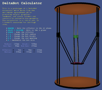
已经失效! Thinkyhead Deltabot calculator 三角洲计算器,输入数字进行模拟。
¶ Rotational deltas
- Parola Java based simulator, rotational delta with many options
- http://arvc.umh.es/label/delta.html
¶ Simulation on software
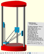
- OpenScad delta simulator for linear delta with active simulation, with common printers datasets predefined. Change variables values for simulation. You can see a film here or here (Fisher Delta)
¶ Delta calculators
¶ Linear deltas
- http://www.heliumfrog.com/deltarobot/details/details.html Excel sheet calculator for linear delta
- https://github.com/Jaydmdigital/mk_visual_calc OpenScad calculator with visualization dedicated to Kossel
¶ Rotational deltas
- marginally clever Online calculator
- Trossen robotics forum
¶ Math and research papers
- File:Rostock Delta Kinematics 3.pdf Comprehensive paper of Steve Graves about linear delta kinematics
- https://groups.google.com/forum/#!topic/deltabot/V6ATBdT43eU Deltabot forum thread on Steve Graves paper with other useful resources
- http://robinsonia.com/wp/?p=161 math explanations for linear delta
- http://scholar.rose-hulman.edu/cgi/viewcontent.cgi?article=1000&context=mechanical_engineering_grad_theses Linear delta research paper, but with the sliders parallel to the effector plan.
Rotational delta are a quite common research topic, notably for university students.
- http://www.ohio.edu/people/williar4/html/pdf/DeltaKin.pdf Rotational delta kinematics.
¶ Calculation links
- https://hackaday.io/project/963-firepick-delta-the-open-source-microfactory/log/3588-6152014-delta-mechanism-simulation-and-accuracy-determination (Rotational delta)
¶ Simulation without source/access
Some people have done Delta simulation on CAD/Math software, but not publicly release them.
- https://www.youtube.com/watch?v=8_6QfZ6DJfU film of a Simulation with Matlab
- https://www.youtube.com/watch?v=K2zxvHq3iC8 film
- https://www.youtube.com/watch?v=OwI6hYHWbjw A python simulator, undisclosed program.
¶ Calibration
- http://forums.reprap.org/read.php?178,639039 Arm length calculation from printing part
- http://escher3d.com/pages/wizards/wizarddelta.php web calculator for calibration parameters
- http://forum.seemecnc.com/viewtopic.php?f=36&t=8698 calculator for calibration parameters
- https://github.com/hercek/Marlin/blob/Marlin_v1/calibration.wxm Calibration calculator running with WxMaxima
- http://forum.seemecnc.com/viewtopic.php?f=82&t=7640 forum thread about Heuristic calibration algorithm